

1. Introduction
Building rehabilitation and renovation are becoming more and more important for the Spanish building sector. As the data shows there has been a total shift in transactions regarding new and used homes (Observatorio de Vivienda y Suelo. Boletín anual 2019, 2019). In 2003 the turnover from the construction of new buildings in Spain was 8.931,1 million euros and 18.558,3 million for restoration and conservation. In 2018 this turnover was 25.693,7 and 30.545,3 million euros respectively. Apart from the general turnover reduction due to the explosion of the housing bubble in Spain in 2009 there has been a change as the investment in renovation is growing while the investment in new housing has been decreasing severely across the last decade. This means that in 2003 the turnover distribution was at 82,4% for new buildings and 17,6% for renovation and in 2018 the distribution was 45,7% and 54,3% respectively.
In the same study, we can also look at the number of transactions regarding new and used houses. The number of transactions has been reduced due to the economic crisis. This reduction has supposed a greater impact on the transaction in new buildings. From 2005 to 2019 there has been a reduction of 48,97% in the number of housing transactions in the Spanish market. The reduction in these operations for new houses was 79,08% and for used ones 25,42% along the same years. Several reasons are causing this change that is listed in the study and are out of the scope of this research, but the tendency is clear, and in the coming years is it easy to think that professional activity is going to grow towards building renovation.
Parallelly, during the same years, there was a change in technology affecting the Architectural, Engineering and Construction Industry (AEC Industry) with the growing adoption of the Building Information Modelling (BIM) paradigm by different professionals. During this last decade, BIM has proven itself to be of value to professionals as it can reduce the time investment by 7% and production costs by 10% (Azhar, 2011). BIM works as an n-dimensional database that stores, relates, shows, and modifies all the parameters in the project allowing the professionals to have complete control over them, their state, and their relationship. BIM environments need a holistic approach and new methodologies. But changes in the project are much easier to implement.
One of the great advantages of BIM is the interoperability that it is capable of. Every parameter in the BIM Model is linked together and altering it automatically updates the whole model. This has made allowed the creation of several Building Performance Simulation Tools (BPS Tools). These, are digital tools with the purpose to analyze and evaluate a certain aspect of the building design and aid the professional in that particular field (Eastman et al., 2011). Most of the research effort related to BIM is centred upon the development of various kinds of these tools and automating the procedures in the AEC Industry. Multi-Criteria Decision Making processes has been an increasing research topic as an automatization measure (Tan et al., 2021). There has been great interest in the use of BIM to improve the structural performance of a building in a BIM environment by optimizing the structural design (Abdalla & Eltayeb, 2018; Eleftheriadis et al., 2017), reducing its cost (Peeraya Inyim et al., 2015), or reducing the CO2 emissions from its construction and improving the general sustainability of the project (Diao et al., 2011). There are also studies to implement the LEED certification in BIM (Wu Wei & Issa Raja R. A., 2015). But the automation of different procedures in BIM can also increment the risk of making mistakes if the professional is not aware of the limitations of the BPS Tool being used, this increases the Black Box Effect (Cauer et al., 2000), reducing the info from the analysis process known by the user, as more automation means more opaqueness in the modelling which can involve several risks (Fernández-Mora, 2018).
1.1 BIM in Building Restoration
Typically, BIM is used to develop projects for new buildings, most of the tools presented earlier aim to help the professionals in the design phase where there is a greater degree of freedom in the design. Using BIM for building restorations has some barriers that have to be overcome related to uncertainty and undefinitions in the knowledge of the building such as material specifications or design purposes. Modelling the building can be a huge investment in time and effort and so, discourage the use of the BIM environment for this purpose (Fernández-Mora & Yepes, 2019)
Despite these barriers, BIM’s abilities to handle time-related data and define objects which are modified along a timeline are really interesting. This is used to implement renovation into BIM in several different ways (Volk et al., 2014) and has led to a new research field in HBIM or BIM for heritage building (Lopez et al., 2018). To create BIM Models for existing buildings technologies like laser-scanning and 3D point cloud (Jung et al., 2016) is being used on several patrimonial buildings (Angulo & Castellano-Román, 2020; Rodrigues et al., 2018). HBIM has also been used to analyze patrimonial structures like vaults (Argiolas et al., 2019) and ancient wooden structures (Jiang et al., 2020).
The growing interest in the renovation building and the ability to perform time-based abilities added to the other advantages of BIM, making it suited for building renovation. The widespread adoption of BIM in these last years by the AEC Industry is also a reason for the professionals to use it more frequently as they are more used to the methodology.
1.2. Structural Expertise
The task to evaluate and study an existing building structure to determine its capabilities to receive the loads and demands which it is being subdued is the structural expertise. It is, in fact, the conclusion at which a professional arrives after performing a methodical and strict analysis following the regulations and represents the structural stability of the building.
To perform structural expertise the professional must study, review, research, and analyze the state of the building and evaluate it to determine if intervention is needed. In case of need, he must also design the solution to solve the detected problem.
1.3. Aim of the paper
According to our knowledge, BIM usage in existing buildings is an open research line. Currently, the research is focused on patrimonial buildings and the creation of accurate 3D Models. There have been shown examples of tools that, analyze the structural behaviour of certain structural elements on the building like vaults or wooden trusses. There hasn’t been any example in the use of BIM to analyze non-patrimonial existing buildings in need of refurbishment.
In this paper, we aim to create a BPS Tool for structural expertise in existing buildings inside BIM environments. This tool is born from the increasing necessity in intervening in the existing buildings and adapting them to new demands as proven by the business changes shown in the Spanish market.
The focus of the paper is to analyze the data recollected by the professionals during the study and help them in the conclusions to evaluate the structural integrity of the studied building. The tool presented in this paper can extract the necessary parameters for the structural expertise in the BIM model, analyze the structural element on its own and set the result on the model. The automation of the process reduces the working time for the professionals, and keeping the data stored in the model reduces errors. By storing the result of the analysis on the BIM Model the data can be consulted at any given time, which the user better control and knowledge about the building and its necessities.
2. Development
To develop a tool able to perform a BPS Tool like previously described a systematic step-by-step approach has been followed to overcome the different barriers in the adoption of BIM for structural expertise. As observed in the bibliographical research the main barrier in the adoption of BIM for structural rehabilitation lies in the uncertainty and the inaccuracy of the model (Fernández-Mora & Yepes, 2019). This gap has to be overcome to guarantee the result of the expertise and the safety of the analyzed structure.
In this regard, we can define this inaccuracy as affecting three different aspects of the data retrieved from the existing structure:
- Uncertainty in the structural behaviour: Referred as the set of inaccuracies due to unknown structural behaviour in the elements.
- Uncertainty in the materials: Inaccuracy in the exact material properties used in the past to build the structure.
- Uncertainty in the design: Uncertainty created by unknowing the design criteria for the original structure.
The plugin is designed so the data has to be used after an inspection of the building has been carried out by the professional, this way data has to be interpreted and pondered by the user before its use. To perform the analysis for a structural element there is a need to collect some data before introducing it in the BIM model. This will allow us to reach a point in knowing where we can be certain of how the structure is working and its characteristics. The collected data will be inputted into the BIM model to recreate its state. The aim is that the structural engineers can perform the expertise by using all the information available to them. The BIM Model summarizes the geometric shape of the object, loads upon it, material properties, and code limits and performs the structural analysis.
3. Workflow for structural expertise
One of the main goals of the tool is to be practical. For this reason, it has been designed in a way that functions according to the workflow followed by professionals. This workflow was previously researched has been used to find the spot where this plugin would properly fit without adding any steps to the current structural expertise workflow.
“Most of the time the professional is contacted by the building’s responsible who exposes the new needs of the building and its actual problems. With that in mind the data collection phase starts, the professional must collect data from the building, its state, possible affection, and if possible, historical data. Once the data is collected, it is time to create a structural model of the building, study the new demands for the structure, and determine the contribution that the existing element can make to the new structure. In case the existing structure proves insufficient for the new loads, reinforcement must be designed and built guaranteeing the right connections between the old and the new parts.” (Fernández-Mora & Yepes, 2019)
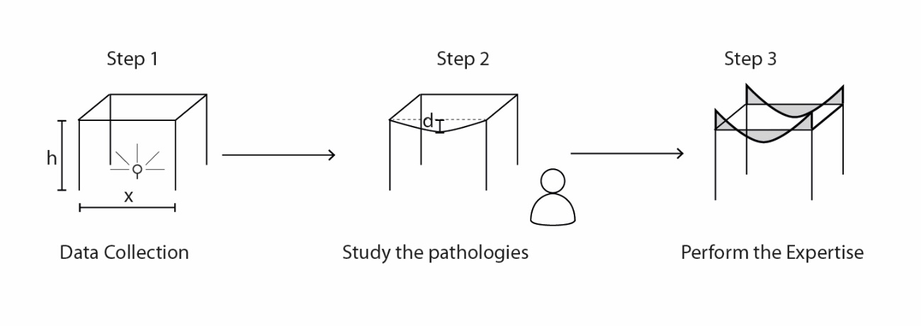
In this article we assume the usage of the tool following the steps that have been defined to perform the expertise:
- Step 1: Collect data from the element. The cross-section dimensions, rebar sizes, and numbers can be collected directly from the model. The materials’ tensile strength can also be studied to create a more accurate model.
- Step 2: Study the possible pathologies and alterations in the element and its new requirements. Any damage shown in the structural element has to be studied to determine its affection depending on the pathology and its causes.
- Step 3: Proceed with the expertise. After collecting the data, the BIM model is created. The model for each structural element contains the retrieved data describing the element and its behaviour. Then the structural analysis is performed on each element that requires it by using the plugin.

The input parameters for the expertise describe the state of the structural element. It is the professional who has to measure the importance of each one based on the beam that is being studied. They have to be quantified and introduced into the BIM model using the Graphic User Interface (GUI) for parameters in families inside Autodesk Revit. This interactive approach leaves in the hands of the professional the definition of the solution space, giving him a certain degree of freedom to model the structural constraints, requirements, and capacities of the model.
There are a minimum number of parameters that need to be defined to develop the expertise. These parameters are the geometrical shape of the element (width, height, and length), its material properties, and the load cases. The structural linkage with adjacent elements can also be defined by the professional upon its knowledge.
4. The difficulty in the structural model
Usually, a structure is designed using theoretical models based on material theory to meet some structural requirements. Later on, it is built following the design reached. It is a translation from the theoretical world to reality. Structural expertise flips this process and the professional must decompose the reality into physical relationships.
The expertise must always be based on the built structure and has to represent the current structural behaviour of an environment. Since its initial theoretical design, it would have suffered a lot of changes, being modification during the building phase (maybe the rebars are placed in a different position or a change in size was needed), or posterior alterations (new constraints or loads may appear during the life cycle of a building). So, the professional must describe the real behaviour of the structure and its conditions, considering the current and new loads and requirements.
Design and working loads are very different. The first one is an estimation given to the professional by the regulations, based on statistical data and security margins. Environment and maintenance affect the lifetime of a concrete structure. Fissures and other pathologies have to be studied before starting the structural analysis. The project is a guideline that provides useful information about the structure and how it was designed to work, but it may not correspond with how it works in reality.
5. Structural model
The scope of the plugin is to perform structural expertise for a concrete beam in an existing building and subject to new loads or conditions. The structural behaviour of the beams can differ after it is built, but their joints will always have a certain degree of stiffness and therefore the ability to transfer bending moment onto the vertical structure.
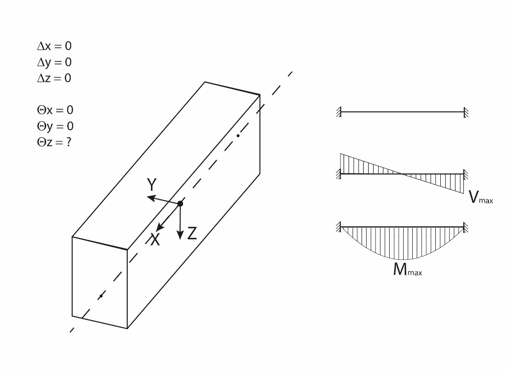
The structural model used for this research is a concrete beam with joints on both endings. The movements in the three axes are considered to be 0 and the rotation for every axis is also restrained to 0 except for the Z-axis. This last axis rotation can be modified by the professional between 0 and 1. Considering 0 a full restriction in the rotation about the Z-axis and 1 that there is no restrain at all.
As the plugin is limited to building structures the loads that can be applied to the beam are limited to uniform loads. These loads cover most of the load cases in building structures. A differentiation between dead and live loads has been made, and the user can apply them separately.

The professional can modify the bending constraints if the element is not well connected enough and has a certain degree of freedom for the movement or if there is any kind of damage. The professional also has to determine the working loads to which the beam is going to be subjected. This opens the analysis to recreate the real behaviour of the structure.
6. BIM Integration
The interoperability between the Finite Element Model (FEM) generated and BIM is key to the success of the BPS Tool as it is an important characteristic of the proposed system. Regarding the BIM environment, Autodesk Revit was used and the FEM tool needed was programmed ad hoc for this research. There is direct interoperability between the FEM Model and the BIM Model as it is possible to transfer design elements, geometric layouts, and material properties back and forth between them.
The integration with BIM is done through the creation of a plug-in able to extract the data from the building model and analyze it considering the different parameters. The interoperability between BIM and FEM analysis has been made guaranteeing the data exchange through a plugin. In this research, C# programming language has been used to access the .NET framework of Revit using Visual Studio 2015 using Revit’s API. The API access provides control over different attributes defined on the BIM model: geometry, model analysis, material properties, load cases, etc. A full list of the extracted parameters will be provided later in this paper.
The data exchange between BIM and FEM is implemented in two different functionalities. The first one is the extraction of the data required to perform the expertise from the BIM model (Downstream) and the second one is the data returned in BIM (Upstream).
First, downstream, the topology of the beam is directly imported from BIM to the FEM without any user interaction, the user-defined parameters must be defined before activating this exchange. Then, after performing the expertise procedure shown in the figure the aptitude of the element to the new structural loads is evaluated and transposed back to BIM, upstream. This info is kept inside the BIM model so the professional can review it later on in case of need without repeating the procedure.

7. Regulations
While structural behaviour is a physical interaction and is the same for the whole globe, one cannot say the same for the structural requirement as they vary for every country and they also influence the final structural design. It is really important to know the historical point in which the building was constructed and the structure designed as this is directly related to the structural design and real behaviour. It is important to define which regulation is used in the structural expertise as it can influence when determining the viability of the structural element and considering it valid for the new structural demands.
Reinforced concrete is a relatively new material as it was widely adopted in the early years of the 20th century. As it became more used more research was done and there were more publications regarding calculus rules or design recommendations. It is not until the second half of the century that regulations start to appear, giving the professionals a common framework for concrete structural design. In this regard, each country had a different development.
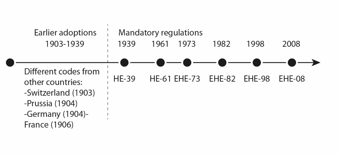
In Spain, the first mandatory regulation was published in 1939 and approved in 1944 with the name Instrucción de Hormigón Armado (Regulation for Reinforced Concrete). Before that year the design was done following earlier codes from other European countries like Switzerland (1903), Prussia (1904), Germany (1904), and France (1906). The code written in 1939 was in use until 1961 when the new code was published adapting the regulations to the new theory of Limit State Design. The regulation maintained the name and was known as HE-61. In the year 1973 the new code, EH-73, added security margins for the material tensile strengths. From there several codes have been published over the years, with changes mostly on building recommendations. There has been a total of four more different codes in the Spanish environment in the years 1982, 1991, 1998, and 2008. This last one, EHE-08 (Instruccion de Hormigón Estructural, EHE-08, 2008), is the one currently in use by the profprofessionals concrete structural design. The next image shows a timeline summarizing the evolution of Spanish concrete regulations across the years.

As time passes the regulations change and its requirements are different. New regulations tend to be more restrictive, implementing new requirements as the knowledge grows. While the structural expertise should be performed using the current regulation, as it is stated in it, it is important to keep in mind the regulation used in the design. Some requirements do not make sense when an existing building is examined with the current regulation as its design rules were different. For example, reinforced concrete structures with a tensile strength lower than 25 MPa were allowed in EHE-73 but not in the current EHE-08, same happens with rebar distribution.
In the examples shown in this article, we have used the requirements and loads for the current regulation in Spain (EHE-08) with some exceptions. The tensile strength for the materials corresponds with the one according to the building period, despite it being inferior to the lower limits allowed nowadays. The different geometrical minimum reinforcement established in the regulation are ignored as they will probably be incoherent with the existing design. In general, structural restrictions are used, while design restrictions are avoided.
Regarding the security margins established by the regulations, we have considered the ones affecting the tensile strength of the material and denied the ones affecting the loads. The materials have suffered degradations procedures by being exposed to the environment and that has to be reflected. On the contrary, the new loads are well-known during the analysis and can be accurately defined and established. Therefore, the decision to ignore security margins affecting the new loads, reducing the overall security margin significantly, to not penalize the structural element in excess. The expertise is then performed with a smaller security margin than the one defined by the regulation.
8. Results
8.1. List of parameters
The list of parameters used to recreate the FEM for the concrete beam cover the design element, geometric layouts, material properties, and load cases upon the studied element. The value of these parameters is embedded in a Revit family created for this purpose and connected to the plugin. In Autodesk Revit, a family is a group of elements with a common set of properties, called parameters, and a related graphical representation.
Based on interoperability among different files, in Autodesk Revit, there are three different kinds of parameters that can be used in its families. Following Revit’s terminology, there are “Project Parameters” that are common for a certain project or file, “Family Parameters” that are shared among the same family in the model, or “Shared Parameters” which can be assigned freely and can be used in different files with the same definition. In the research, we have used “Shared Parameters” as they can share their properties among different files and it’s easier to extract them externally, as they are always referred to in the same way in the API. These parameters can contain any kind of data, either numeric or text entries. In the presented plugin, only numeric parameters have been used. A complete list of the parameters and their definition can be found in Table 1.
Geometrical parameters contain data that can be measured in space, and so it is represented in the BIM Model. Non-geometrical ones contain data describing properties of the element and can’t be visualized in Revit’s GUI, but can be accessed and edited from there. One of the risks to automating the structural expertise is that the FEM created and analyzed may not represent reality. The chosen parameters make it possible to model an accurate FEM including some issues that the element may have suffered such as material properties degradation, geometrical variations, or excessive bending. With these parameters, the user can represent the real state of the beam and avoid the Black Box Effect derived from the automation of this procedure.
The Embedment Coefficient plays a key role in representing the real behaviour of the beam. Its value varies from 0 to 1 and represents the embedment of the element with the rest of the structure. This parameter measures the capability of the beam to redistribute the bending force to another element where it connects. If considered 0, the connection will behave like a hinge, if considered 1 it will behave as a rigid connection, any in-between value will act as semi-rigid.
9. Case Studies
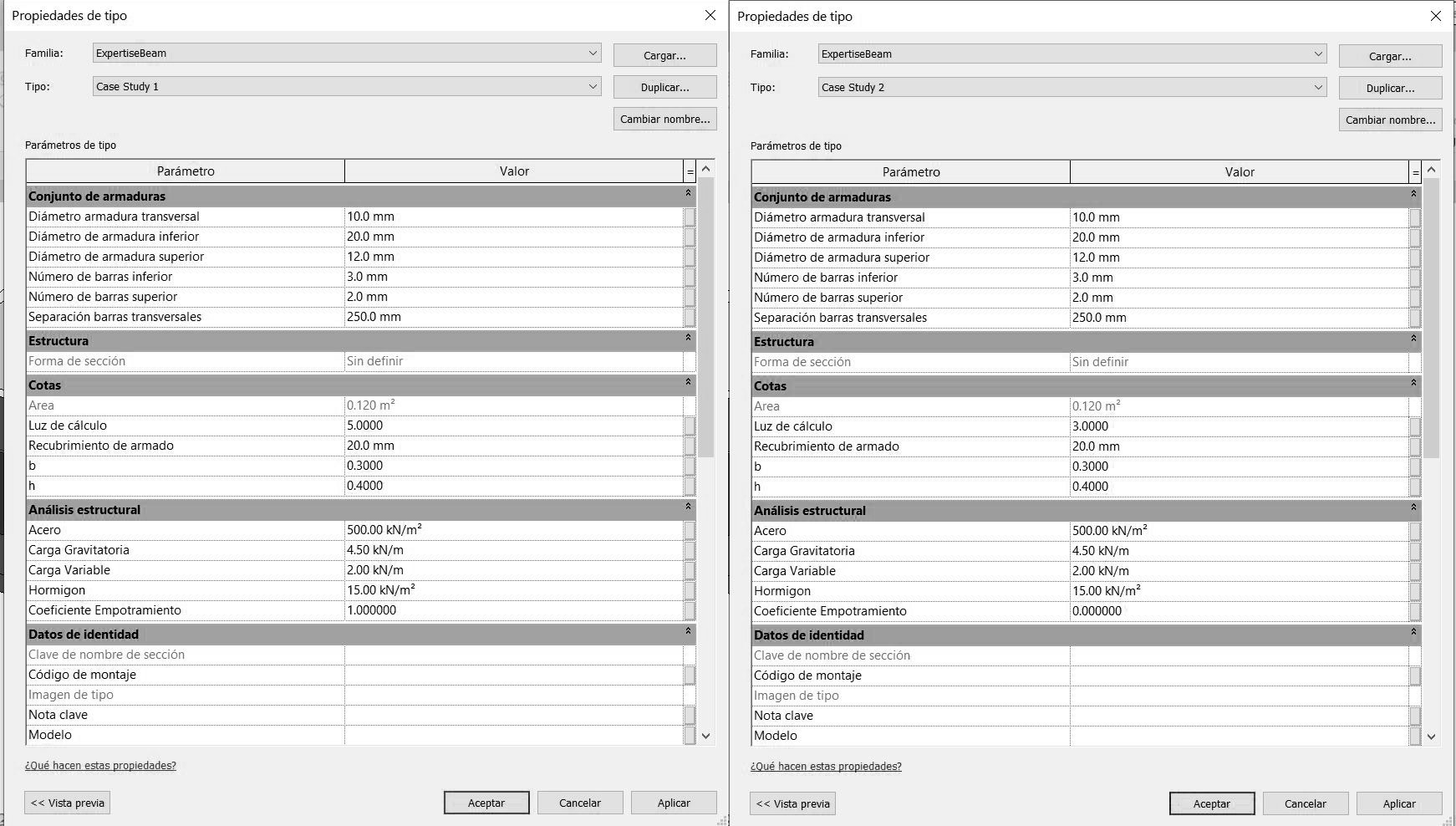
The case example presented in this paper is a theoretical residential building in Spain. Only one of the apartments has been modelled in BIM as shown in the following images. The concrete beam has a cross-section of 0,3x0,4 meters and starts and finishes on two columns, its rebar reinforcement is shown in the image. There is no damage affecting the transmission of the bending but some material degradation (the concrete tensile strength considered is 15 N/mm2). The load cases in the building include dead loads and live loads. The loads considered follow the Spanish regulations for the residential areas: dead load is 4,5 KN/m2 and live load is 2,0 KN/m2. The loads are uniformly distributed on the whole floor and the bay distances are 5 and 3 m.

_and_case_study_2_(right).png)
In the same dwelling, we are going to perform tests upon two different beams. The first beam has a total span of 5 m. and it presents no pathologies of any sort, so the Embedment Coefficient considered has the value of 1. The second beam has suffered from creep issues and has an excess deflection. As a result, some part of the load from the beam has been carried by the wall under it had made some cracks in it. In this second case, we have a reduced span of 3 m. but we cannot guarantee the right embedment of the beam, so the value of the coefficient is 0.
10. Analysis of the results
After performing the expertise, the plugin output the result indicating the aptitude or not of the element and informing the professional of it. This is shown through a window with a text that states the result of the test. The result is then stored in the parameter named “Viability” inside the family. After performing the tests on the two case studies the results are the following.
After performing the expertise, the “Viability” for both study cases is 1, meaning that both are sufficient to handle their new demands upon their new constraints. Neither of them requires a structural reinforcement. Case Study 1 has been modelled following a “healthy” hypothesis, where the beam has not suffered any damage through its life cycle. It is considered a control element, validating the design of the structure. On the other hand, Case Study 2, suffered some pathologies during its lifecycle, losing its perfect embedment with supports. Despite that, it had found a stable state by unloading some load onto a wall. While both structural elements are structurally stable, they are not in the same situation. Case Study 2 has suffered an important alteration and it needs further study to establish if the degradation process has stopped or can increase.
The parameter “Viability” value is stored inside each one of the elements studied. This output parameter has been added so it can be reviewed later on straightforwardly. This parameter can be listed in the BIM model to obtain a table that relates the structural feasibility of the element and the description of the element, making use of BIM’s natural interoperability. After performing the expertise in the different structural objects, it can be easily tracked which elements are valid and which ones do require structural reinforcement to be able to function and to support the new demands.
11. Conclusion
In this paper, an Autodesk Revit plugin able to perform structural expertise on a single concrete beam has been developed and tested on two separate case studies. This plugin extracts the data from the BIM Model, performs the analysis, and introduces back the result, informing the professional of the suitability of the element to support the new demands. The tool presented is in a preliminary phase of development, right now it can perform the task, but more study cases have to be tested to ensure the feasibility of its results.
In the current version, the data extracted is defined by the user and contains the size of the element, material properties, load case, and conservation state, represented by the embedment coefficient. The parameters introduced to perform the expertise have been selected to allow the professional to recreate the actual state of the element including pathologies that could have affected it through its life cycle.
As presented, the analysis tool has been limited to analysis only isolated concrete beams. This limitation has been established to help the professional to perform more accurately expertise. By editing the parameter values the user may alter the FEM used for the analysis and customize it to reflect the real state of the structure.
In the paper, two examples have been shown of how the tool works and integrates the results into the BIM Model. The different examples show the failure of the element and its acceptance. The analysis covers all the structural requirements defined nowadays by the Spanish concrete regulation EHE-08 with the exceptions regarding minimum reinforcement required.
11.1. Scalability to the whole structure
The plugin presented in this paper can only perform the structural expertise of a single structural element. This has been a design decision. The structural expertise must be performed with care and each element has to be evaluated before deciding if it is necessary to analyze it, this decision relies upon the professional. The BIM and the FEM can be done considering the whole structure, but it becomes more and more difficult as the structure grows to consider the different conditions of each element. Further research is needed in this field to determine if the advantages of performing whole structure expertise are enough despite the difficulty in the model and how to deal with the issues related to the different elements being in different conditions.
11.2. Future research lines
The plugin presented in the paper performs the structural expertise for a single structural element evaluating if it is fitted or not for the new structural demands. Further research is required to study and develop an environment inside BIM able, not only to perform the structural expertise for a single element but also to help the professional in the design of the structural reinforcement when it is needed. Further research is also needed to determine the critical points that have proven insufficient by the structural expertise and optimize the needed structural reinforcement. The plugin presented in this paper is a preliminary phase of ongoing research, more development is needed to ensure and guarantee the results and its suitability to be used by professionals.